12/09/2025 4:53 p.m.
https://cablematic.com/en/products/overvoltage-protector-and-electric-shock-ethernet-rj45-10ka-dw-0500-AO040/
https://cablematic.com/en/products/overvoltage-protector-and-electric-shock-ethernet-rj45-10ka-dw-0500-AO040/
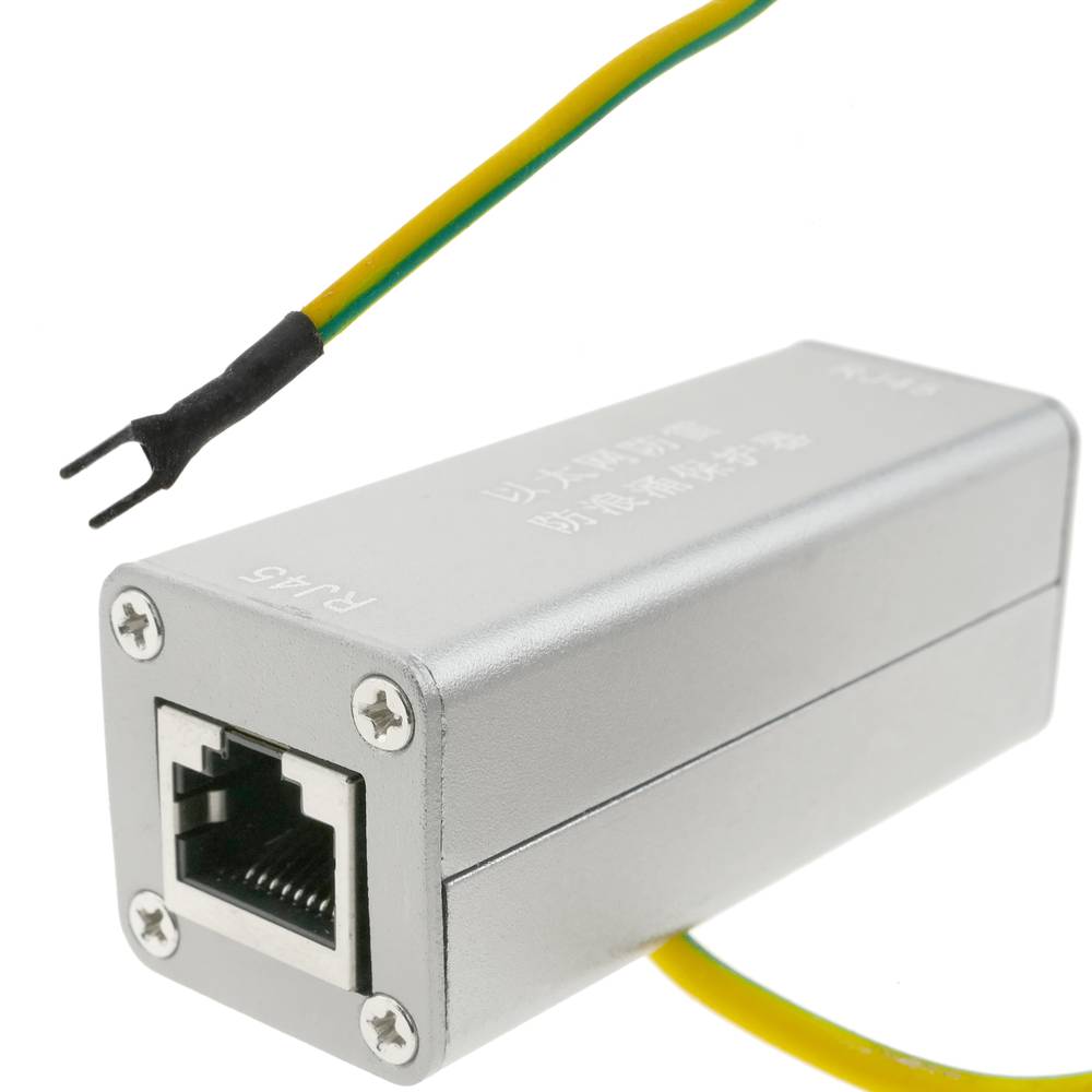
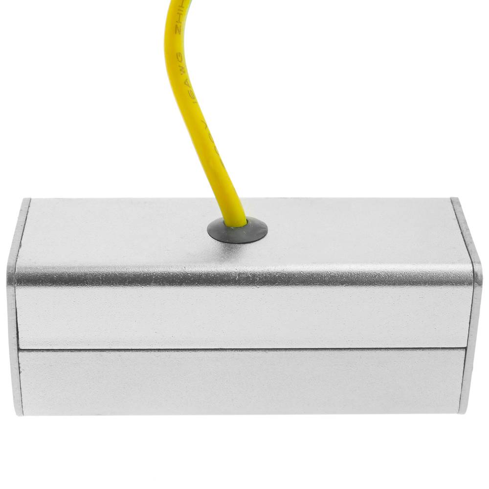
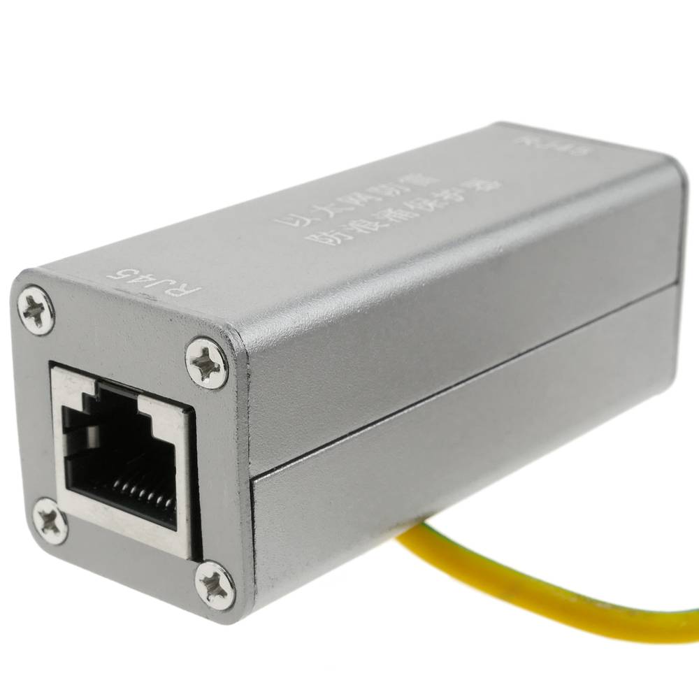
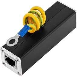
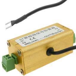
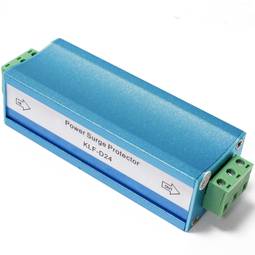
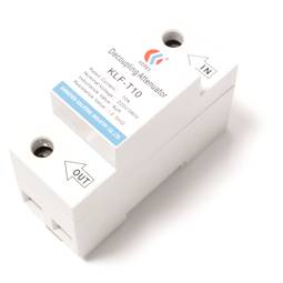
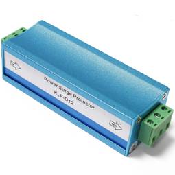
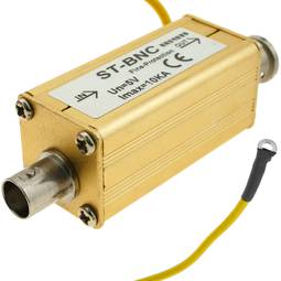
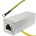
Overvoltage protector and electric shock. Ethernet RJ45 10KA DW-0500
REF: AO040
Specifications
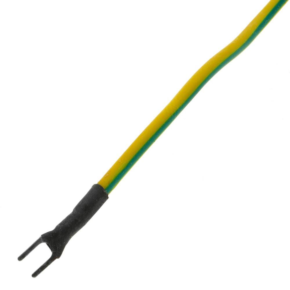
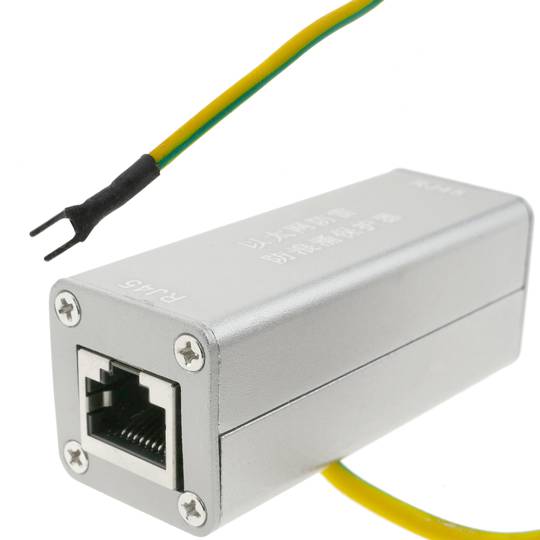
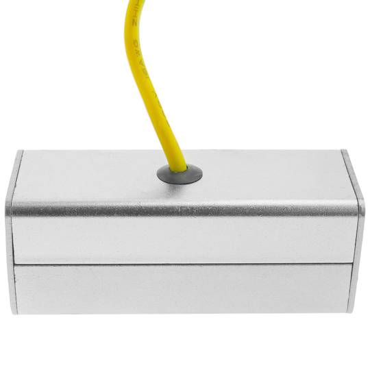
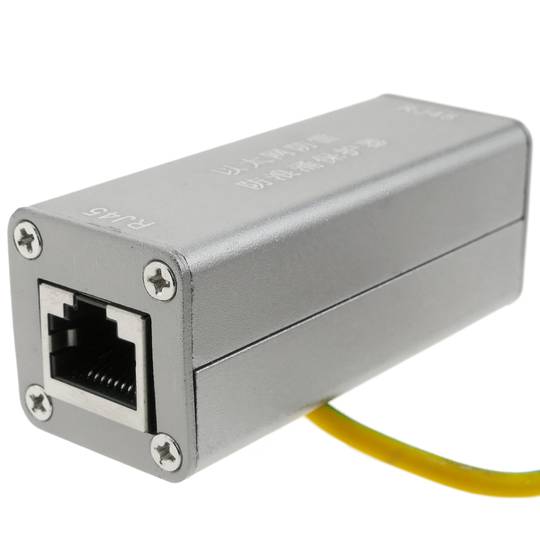
- Overvoltage and electrical discharge protector, for Ethernet RJ45 10KA, model DW-0500.
- Approximate size: 25 x 67 x 25 mm.
- Device designed for integrators.
- High quality electronic components.
![play_button]() Watch video
Watch video
More info
PVP
€18.36
Price including VAT:
€18.36
PVD
€15.56
PVP: Retail price.
Check conditions.
PVP: Sale price to distributors.
Check conditions.
warranty
returns
safe
We will notify you when it is back in stock.
Specifications
- Overvoltage and electrical discharge protector, for Ethernet RJ45 10KA, model DW-0500.
- Approximate size: 25 x 67 x 25 mm.
- Device designed for integrators.
- High quality electronic components.
Keywords
Did not find what you were looking for? These topic could help you
More info
Overvoltage and electrical discharge protector, for Ethernet RJ45 10KA, model DW-0500. Approximate size: 25 x 67 x 25 mm. Device designed for integrators. High quality electronic components.
- Gross Weight: 70 g
- Product size (width x depth x height): 2.5 x 6.7 x 2.5 cm
- Number of packages: 1
- Packages size: 9.6 x 4.0 x 2.8 cm
Technical terms
- RJ45
- Categories network cables
RJ45
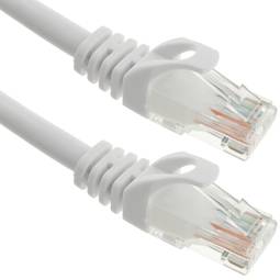
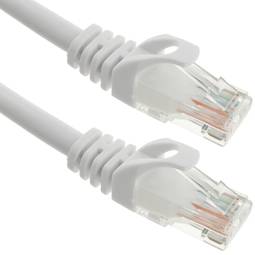
When we talk about RJ45 ("Registered Jack" 45) we refer to a telecommunications network interface for wired connection of voice and data equipment.
This connector has 8 pins or connections and may have a specific category depending on the data transfer speed and bandwidth (category 5e, 6, etc.)
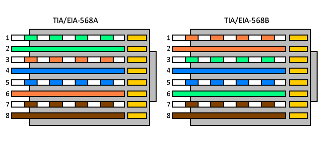
The common application is their use in Ethernet network cables under TIA/EIA-568-B standard that defines the arrangement of pins (pinout), but can also be used for other applications.
- Direct pin diagram:
EIA-568A
Pin No.1: WHITE-GREEN
Pin No.2: GREEN
Pin No.3: WHITE-ORANGE
Pin No.4: BLUE
Pin No.5: WHITE-BLUE
Pin No.6: ORANGE
Pin No.7: WHITE-BROWN
Pin No.8: BROWN
EIA-568B
Pin No.1: WHITE-ORANGE
Pin No.2: ORANGE
Pin No.3: WHITE-GREEN
Pin No.4: BLUE
Pin No.5: WHITE-BLUE
Pin No.6: GREEN
Pin No.7: WHITE-BROWN
Pin No.8: BROWN
- Schematic of crossed pins:
The crossover cable has one end with EIA-568A scheme and the other one with EIA-568B.
