

https://cablematic.com/en/products/diverter-taps-sattv-2-way-10db-TT057/


Diverter (Taps) SAT/TV 2-Way (10dB)

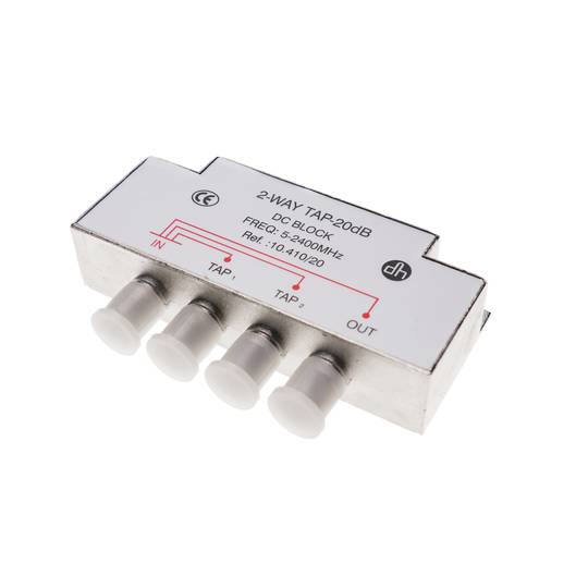
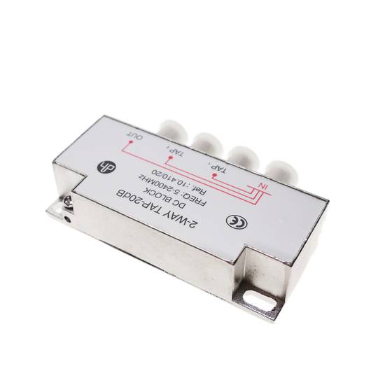
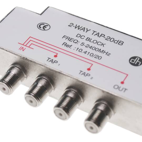
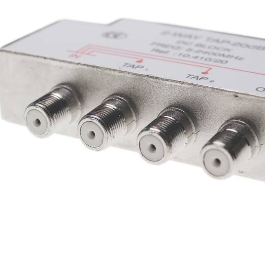
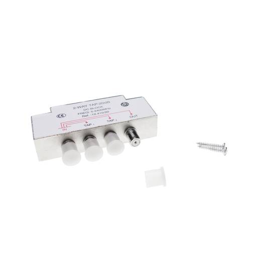
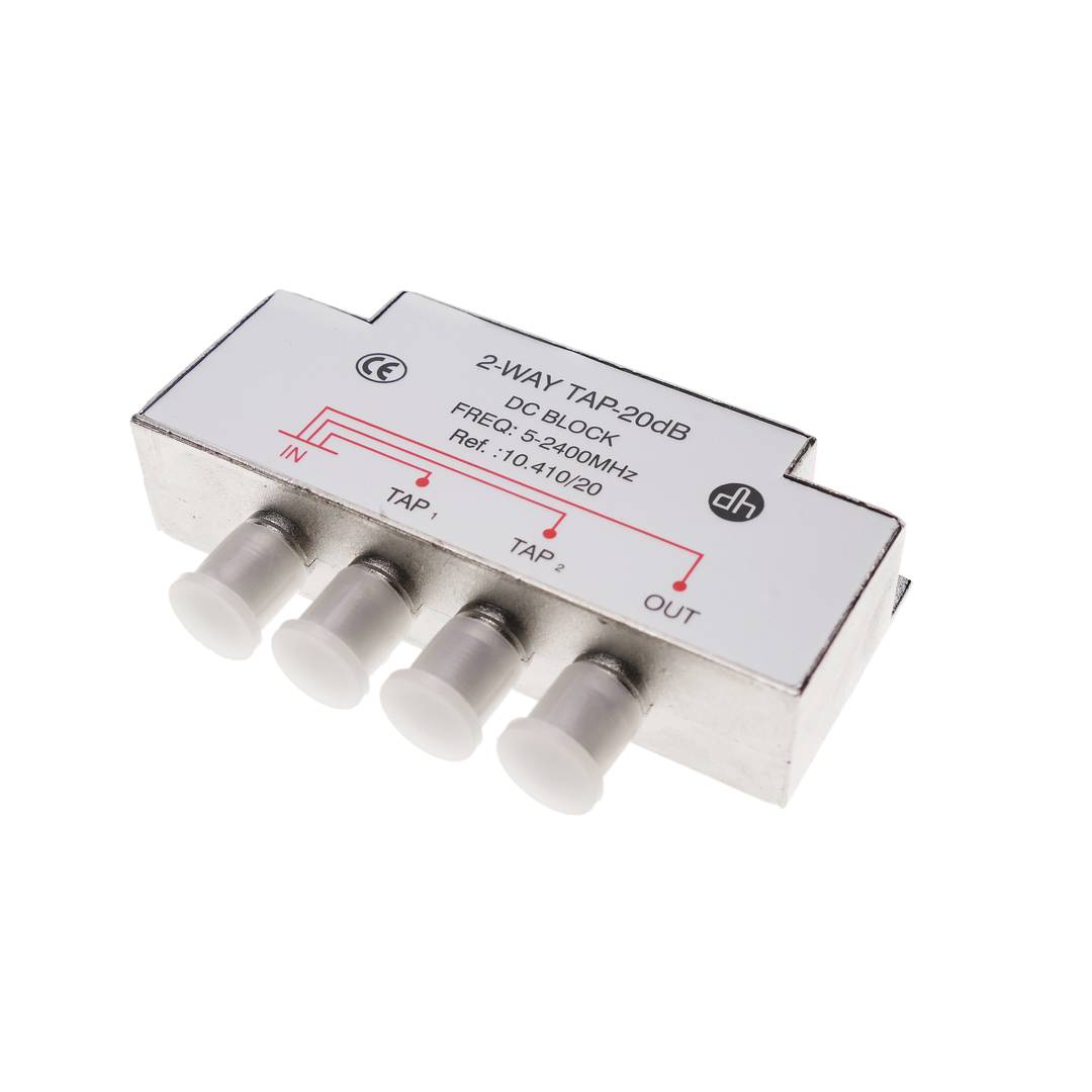
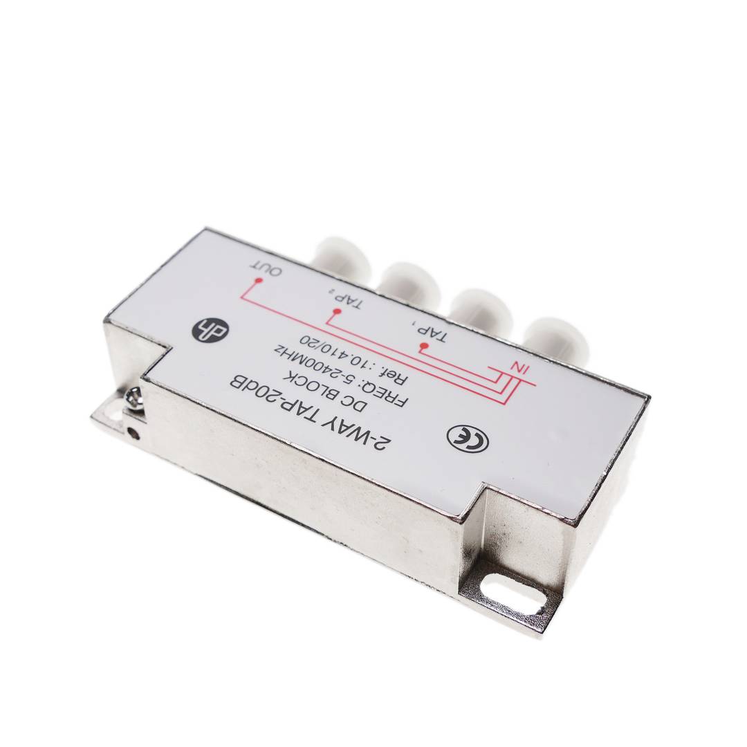
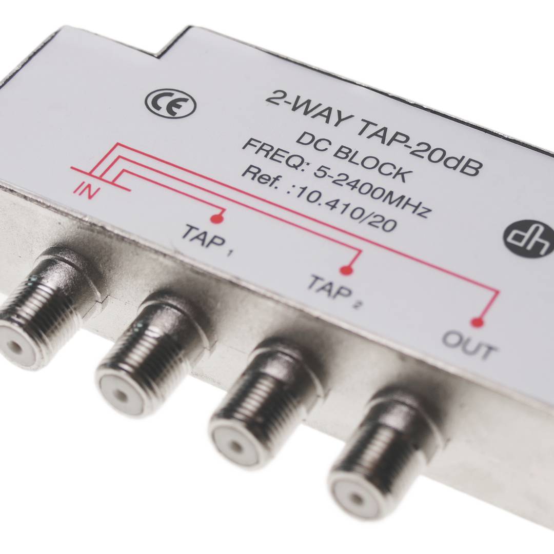
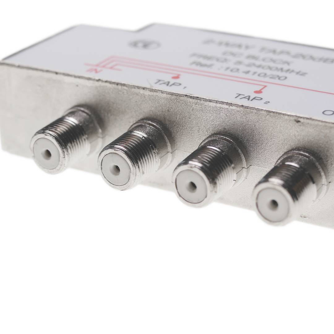
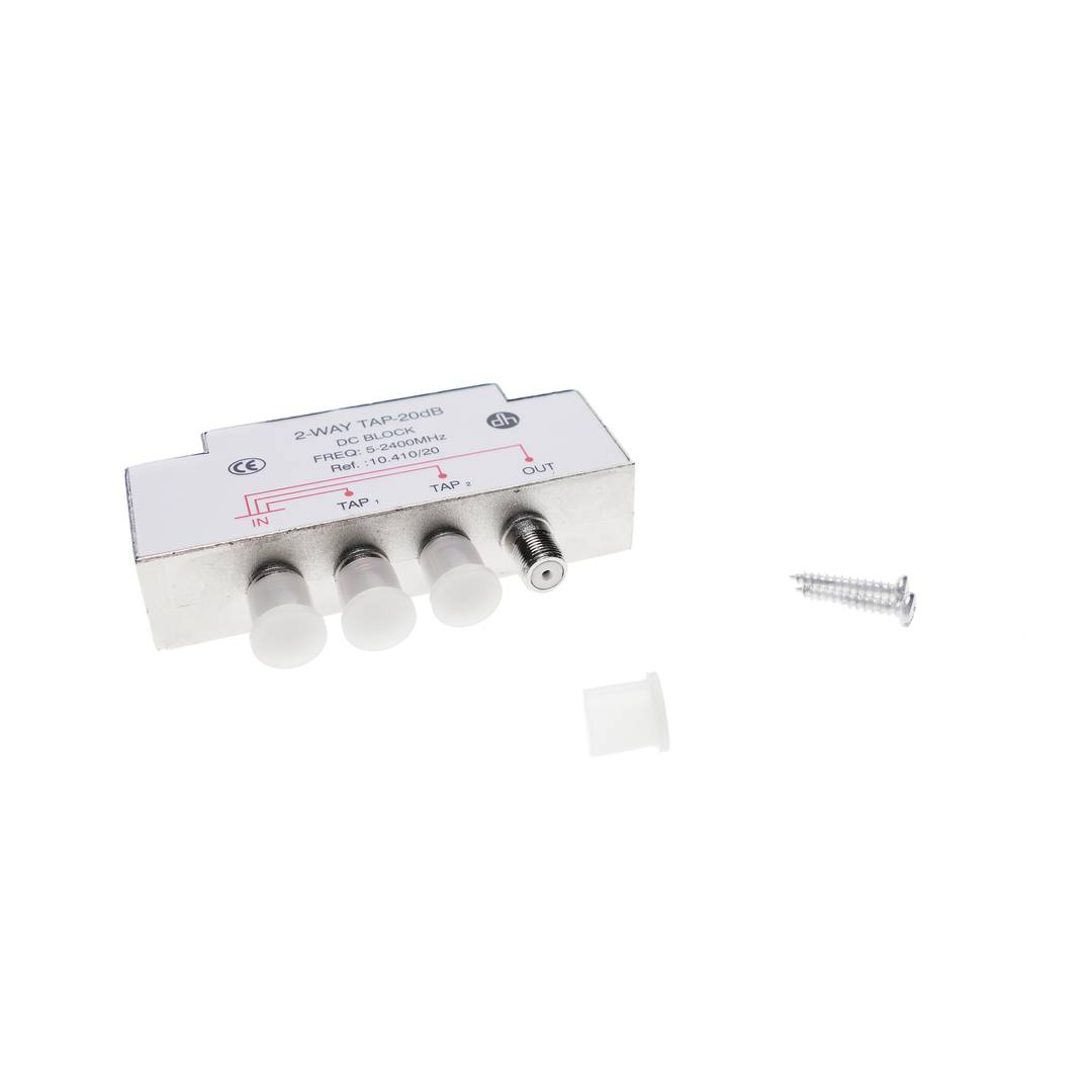
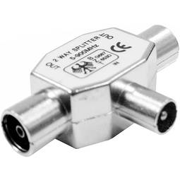
- Shunt (TAPS) 2-way TV signal from satellite or terrestrial.
- Mounted zinc die casing.
- Impedance of 75 Ohms and frequency of work pass 5-2400 MHz Attenuation TV/FM of 1.9 dB, attenuation of 4.0 dB step SAT, decoupling attenuation and attenuation 10.0 dB of return greater than 20.0 dB.
- Size 82 x 56 x 14 mm.
- It has 1 IN, 1 OUT and TAP-OUT 2.
![play_button]() Watch video
Watch video
More info
 Watch video
 2 years
warranty
 14 days
returns
 100%
100%safe
- Shunt (TAPS) 2-way TV signal from satellite or terrestrial.
- Mounted zinc die casing.
- Impedance of 75 Ohms and frequency of work pass 5-2400 MHz Attenuation TV/FM of 1.9 dB, attenuation of 4.0 dB step SAT, decoupling attenuation and attenuation 10.0 dB of return greater than 20.0 dB.
- Size 82 x 56 x 14 mm.
- It has 1 IN, 1 OUT and TAP-OUT 2.
Related products
More info
Shunt (TAPS) 2-way TV signal from satellite or terrestrial. Mounted zinc die casing. Impedance of 75 Ohms and frequency of work pass 5-2400 MHz Attenuation TV/FM of 1.9 dB, attenuation of 4.0 dB step SAT, decoupling attenuation and attenuation 10.0 dB of return greater than 20.0 dB. Size 82 x 56 x 14 mm. It has 1 IN, 1 OUT and TAP-OUT 2. Model based on F connectors
- Gross Weight: 160 g
- Product size (width x depth x height): 9.5 x 6.0 x 2.0 cm
- Number of packages: 1
- Packages size: 9.5 x 9.0 x 3.0 cm
Technical terms
- Impedance
- Hz
Impedance (Z) is the total opposition that a circuit offers to alternating current (AC) flow when a specific voltage is applied.
Unlike simple resistance, impedance is a complex quantity comprising resistance (the real part) and reactance (the imaginary part, representing inductive or capacitive effects). In the frequency domain, impedance is represented as a phasor, accounting for both magnitude and phase shift between voltage and current. In DC circuits, impedance reduces to pure resistance with zero phase angle.
| Parameter | Technical Spec |
|---|---|
| Symbol | Z |
| Unit | Ohm (Ω) |
Impedance management is critical in high-speed hardware design and signal integrity. In modern PCB manufacturing, controlled impedance ensures that high-frequency signals reach their destination without reflections, which is vital for PCIe or DDR5 performance.
Complex Domain Analysis
Mathematical modeling of impedance using the j-operator allows engineers to optimize filter performance and resonance characteristics in electronic systems.
Key Advantages
- Maximum power transfer through impedance matching.
- Minimized signal reflections in high-frequency transmission lines.
- Improved electromagnetic compatibility (EMC).
Note: Impedance is the cornerstone of modern AC circuit theory and high-frequency design.