https://cablematic.com/en/products/pce-ite-50-installation-tester-PC126/


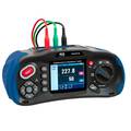
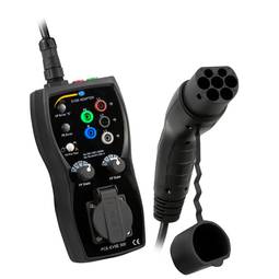
PCE-ITE 50 installation tester


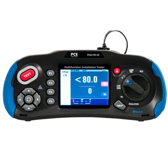

- Rugged installation tester.
- 3.5 color TFT-LCD screen.
- Measurement modes: insulation resistance, earth resistance, loop impedance, voltage measurement, low impedance measurement, and DDR test with camera function.
- Documentation of the measurement with photos.
- Measurement of low ohm values with frequency 0...2000 and resolution 0.001...1.
warranty
returns
safe
- Rugged installation tester.
- 3.5 color TFT-LCD screen.
- Measurement modes: insulation resistance, earth resistance, loop impedance, voltage measurement, low impedance measurement, and DDR test with camera function.
- Documentation of the measurement with photos.
- Measurement of low ohm values with frequency 0...2000 and resolution 0.001...1.
Related products


Keywords
Did not find what you were looking for? These topic could help you
More info
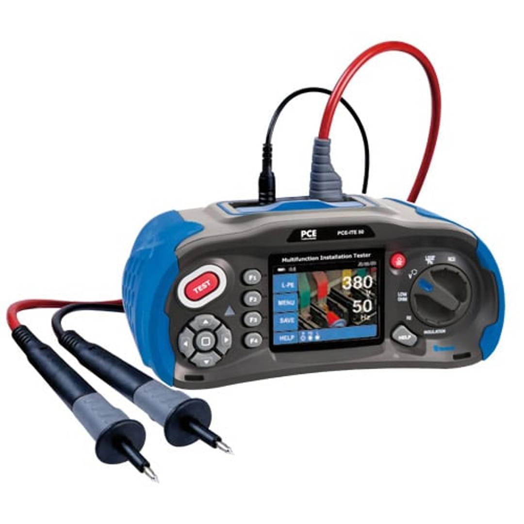
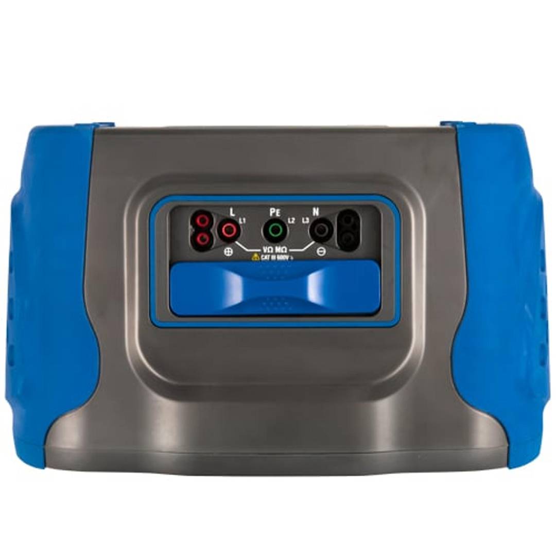
The loop impedance measurement is made with a test voltage of 10 V. This measurement is useful for checking grounding installations, since the loop resistance should be as low as possible. The installation tester offers the possibility to measure line voltages and phase connections with a test voltage of 1000 V AC/DC. This function is used to check the continuity and resistance of circuits. The installation tester also offers the possibility to perform the DDR (Network Diagnostic) test. This test is used to check the resistance of line, ground and neutral conductors. This test is carried out with a test voltage of 250 V AC/DC. The installation tester also offers the possibility of making low impedance measurements with a test voltage of 10 V. This function is useful for checking the proper functioning of safety devices, such as differentials. To check the correct installation of safety devices, the installation tester offers the possibility of making a low impedance measurement. This measurement is carried out with a test voltage of 10 V. It is a robust device that offers a wide variety of measurements to verify the correct installation of fixed installations. It has a large 3.5 color TFT-LCD display, intuitive symbols, high degree of vision, insulation resistance measurement, earth resistance, loop impedance, voltage measurement, low ohm measurement, DDR test and camera function. These features allow the user to perform comfortable and fast measurements, as well as to document the measurement with the corresponding photos. These features help ensure that fixtures are installed safely and correctly. The installation tester is a robust and reliable device to guarantee the safety and correct installation of all electrical systems. Manufactured by PCE with reference PCE-ITE 50.
Specifications
- Rugged installation tester.
- 3.5 color TFT-LCD screen.
- Measurement modes: insulation resistance, earth resistance, loop impedance, voltage measurement, low impedance measurement, and DDR test with camera function.
- Documentation of the measurement with photos.
- Measurement of low ohm values with frequency 0...2000 and resolution 0.001...1.
- Insulation resistance measurement with 125V, 250V, 500V or 1000V test voltage and 1mA test current.
- Earth resistance measurement with measuring range 0...2000 and resolution 0.01...1 .
- Ideal for ensuring that fixed installations are installed safely and correctly
- Gross Weight: 5.169 kg
- Number of packages: 1
Technical terms
- Impedance
Impedance (Z) is the total opposition that a circuit offers to alternating current (AC) flow when a specific voltage is applied.
Unlike simple resistance, impedance is a complex quantity comprising resistance (the real part) and reactance (the imaginary part, representing inductive or capacitive effects). In the frequency domain, impedance is represented as a phasor, accounting for both magnitude and phase shift between voltage and current. In DC circuits, impedance reduces to pure resistance with zero phase angle.
| Parameter | Technical Spec |
|---|---|
| Symbol | Z |
| Unit | Ohm (Ω) |
Impedance management is critical in high-speed hardware design and signal integrity. In modern PCB manufacturing, controlled impedance ensures that high-frequency signals reach their destination without reflections, which is vital for PCIe or DDR5 performance.
Complex Domain Analysis
Mathematical modeling of impedance using the j-operator allows engineers to optimize filter performance and resonance characteristics in electronic systems.
Key Advantages
- Maximum power transfer through impedance matching.
- Minimized signal reflections in high-frequency transmission lines.
- Improved electromagnetic compatibility (EMC).
Note: Impedance is the cornerstone of modern AC circuit theory and high-frequency design.