

https://cablematic.com/en/products/roof-antenna-700-to-2500-mhz-3-dbi-AP052/

 2 years
warranty
 14 days
returns
- Operating frequency: 700 to 2500 MHz.
- Gain: 3 dBi.
- VSWR: <= 2.0.
- Radial anglehorizontal: 360 °.
- Vertical radiation angle: 75 °.
Related products
Keywords
Did not find what you were looking for? These topic could help you
More info
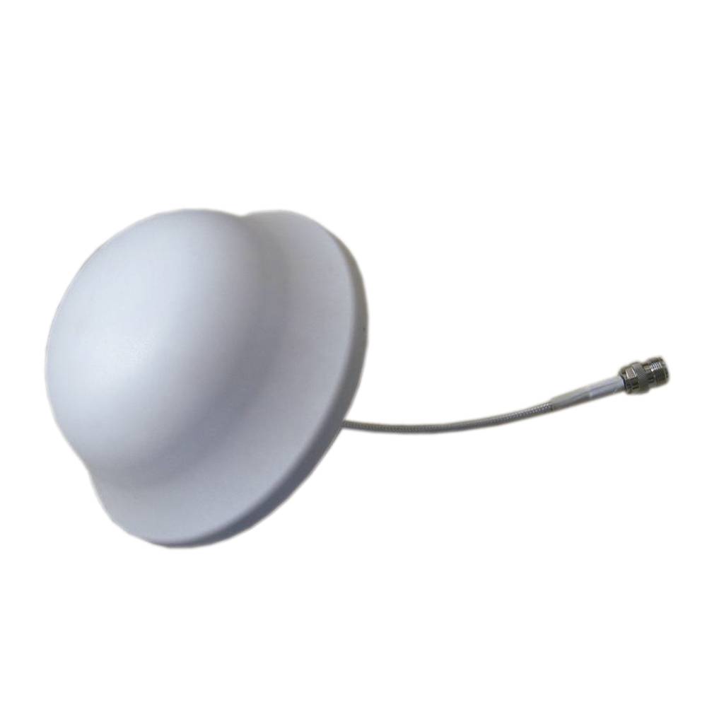
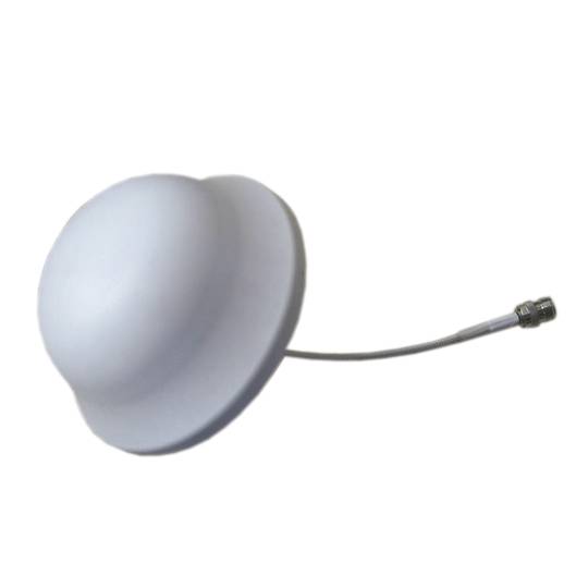
Omnidirectional ceiling antenna with 3 dBi gain and operating frequency from 700 to 2500 MHz. Made of light but resistant ABS plastic. Compact model designed to be mounted on the roof. It has a screw-type ceiling fixing system integrated in the antenna itself.
Specifications
- Operating frequency: 700 to 2500 MHz.
- Gain: 3 dBi.
- VSWR: <= 2.0.
- Radial anglehorizontal: 360 °.
- Vertical radiation angle: 75 °.
- Polarization: Vertical.
- Impedance: 50 Ohm.
- Maximum power input: 100 W.
- Connector: N female in hose of 25 cm in length.
- Antenna size: 167 x 80 mm.
- Weight: 0.4 Kg.
- Gross Weight: 340 g
- Number of packages: 1

Technical terms
- Impedance
- Hz
- ABS
- dBi
Impedance (Z) is the total opposition that a circuit offers to alternating current (AC) flow when a specific voltage is applied.
Unlike simple resistance, impedance is a complex quantity comprising resistance (the real part) and reactance (the imaginary part, representing inductive or capacitive effects). In the frequency domain, impedance is represented as a phasor, accounting for both magnitude and phase shift between voltage and current. In DC circuits, impedance reduces to pure resistance with zero phase angle.
| Parameter | Technical Spec |
|---|---|
| Symbol | Z |
| Unit | Ohm (Ω) |
Impedance management is critical in high-speed hardware design and signal integrity. In modern PCB manufacturing, controlled impedance ensures that high-frequency signals reach their destination without reflections, which is vital for PCIe or DDR5 performance.
Complex Domain Analysis
Mathematical modeling of impedance using the j-operator allows engineers to optimize filter performance and resonance characteristics in electronic systems.
Key Advantages
- Maximum power transfer through impedance matching.
- Minimized signal reflections in high-frequency transmission lines.
- Improved electromagnetic compatibility (EMC).
Note: Impedance is the cornerstone of modern AC circuit theory and high-frequency design.