https://cablematic.com/en/products/rs485-module-with-8-digital-inputs-and-8-digital-outputs-trp-c29-TI074/

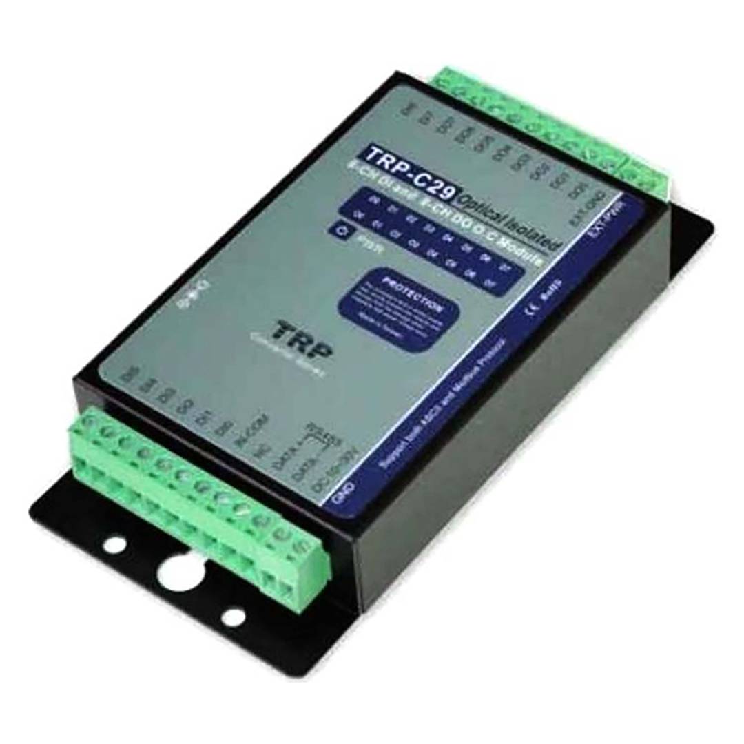


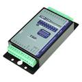
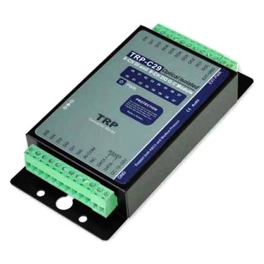
RS485 module with 8 digital inputs and 8 digital outputs (TRP-C29)


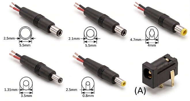
- Direct power through the terminals or external power supply via DC jack (source not included).
- Supports ASCII and Modbus RTU protocols.
- Supports data transmission speeds from 1.2 Kbps to 115.2 Kbps
- The 8 digital input channels can be used as counters (Dec. 0 to 65535 or Hex. 0000 to FFFF).
- Optical isolation of digital input signals up to 3750 Vrms.
warranty
returns
safe
- Direct power through the terminals or external power supply via DC jack (source not included).
- Supports ASCII and Modbus RTU protocols.
- Supports data transmission speeds from 1.2 Kbps to 115.2 Kbps
- The 8 digital input channels can be used as counters (Dec. 0 to 65535 or Hex. 0000 to FFFF).
- Optical isolation of digital input signals up to 3750 Vrms.
Keywords
Did not find what you were looking for? These topic could help you
More info
Device with RS485 interface that has 8 opto-isolated digital inputs and 8 digital outputs. Each channel has a terminal connection and an LED indicating the status of the channel. The input channels are equipped with an opto-isolation DC of up to 3750 Vms. It supports the ASCII and Modbus communication protocols with a complete set of commands, dual watchdog and auto-reset function. The module can be bi-dDirectionally controlled remotely by a PC using either the ASCII protocol or the Modbus RTU.
Specifications
- Direct power through the terminals or external power supply via DC jack (source not included).
- Supports ASCII and Modbus RTU protocols.
- Supports data transmission speeds from 1.2 Kbps to 115.2 Kbps
- The 8 digital input channels can be used as counters (Dec. 0 to 65535 or Hex. 0000 to FFFF).
- Optical isolation of digital input signals up to 3750 Vrms.
- Dual watchdog: in the firmware and in the traffic between the computer.
- Status LED for each of the input and output channels (total 16 LED).
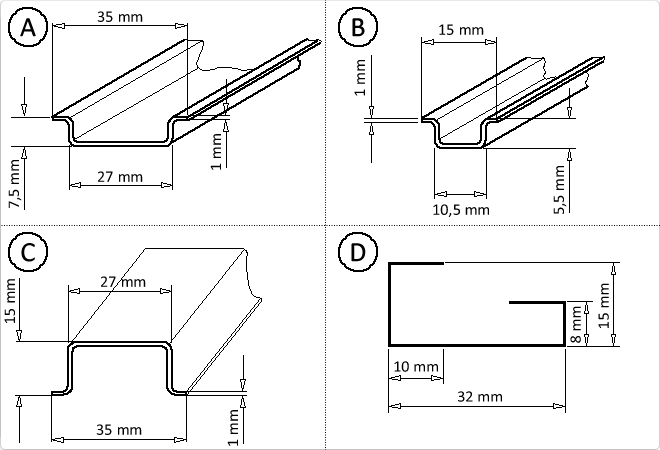
- Supports mounting on DIN rail or directly on the wall.
- It has a dip-switch for configuration and self-test.
- It has connection terminals for the realization of digital input and output connections.
- Logical input level 0: ± 1 V (max).
- Logical input level 1: ± 4 V to ± 30 V.
- Input impedance: 3 Kohm.
- Input counter frequency: 100 Hz.
- Maximum entry distance: 500 m.
- Maximum voltage ofOutput: ± 30 V.
- Maximum output current: 100 mA.
- Consumption: 1.2 W.
- Size: 151 x 75 x 26 mm.
- Weight: 400 g
- Mounted in black metal casing.
- Gross Weight: 410 g
- Number of packages: 1
Technical terms
- Impedance
- DC jack connector
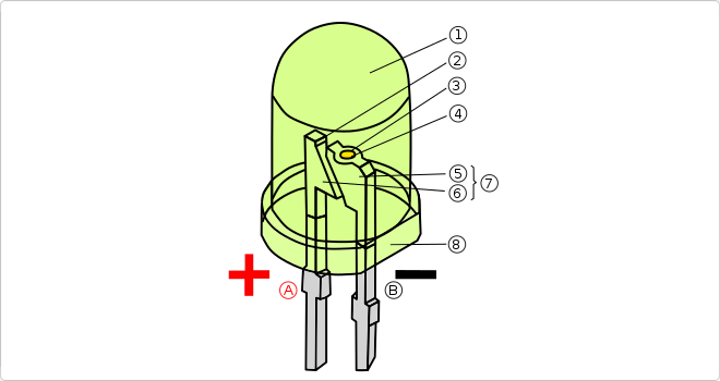
- LED
- Hz
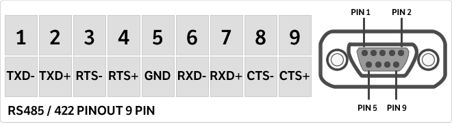
- RS485
- DIN
- DIN Rail
Impedance (Z) is the total opposition that a circuit offers to alternating current (AC) flow when a specific voltage is applied.
Unlike simple resistance, impedance is a complex quantity comprising resistance (the real part) and reactance (the imaginary part, representing inductive or capacitive effects). In the frequency domain, impedance is represented as a phasor, accounting for both magnitude and phase shift between voltage and current. In DC circuits, impedance reduces to pure resistance with zero phase angle.
| Parameter | Technical Spec |
|---|---|
| Symbol | Z |
| Unit | Ohm (Ω) |
Impedance management is critical in high-speed hardware design and signal integrity. In modern PCB manufacturing, controlled impedance ensures that high-frequency signals reach their destination without reflections, which is vital for PCIe or DDR5 performance.
Complex Domain Analysis
Mathematical modeling of impedance using the j-operator allows engineers to optimize filter performance and resonance characteristics in electronic systems.
Key Advantages
- Maximum power transfer through impedance matching.
- Minimized signal reflections in high-frequency transmission lines.
- Improved electromagnetic compatibility (EMC).
Note: Impedance is the cornerstone of modern AC circuit theory and high-frequency design.