https://cablematic.com/en/products/surge-protector-antenna-coaxial-type-n-10ka-SP072/


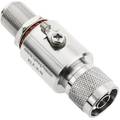
Surge Protector antenna coaxial type N 10KA

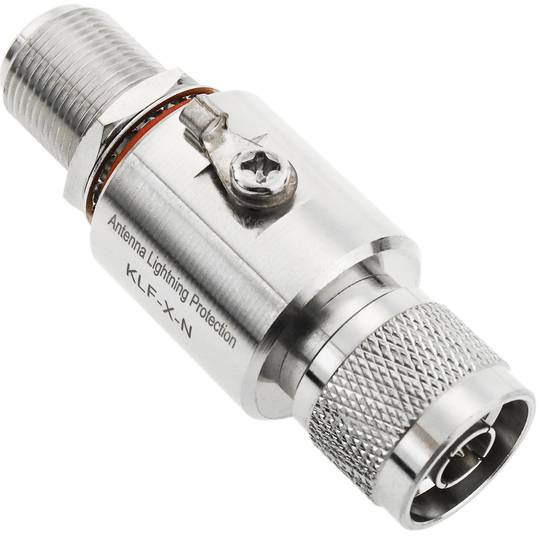
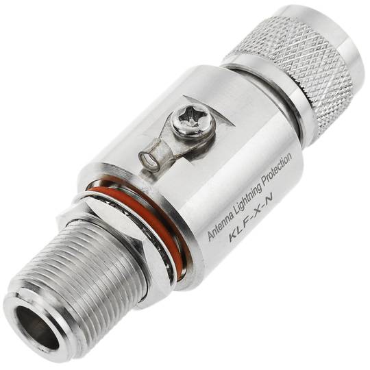


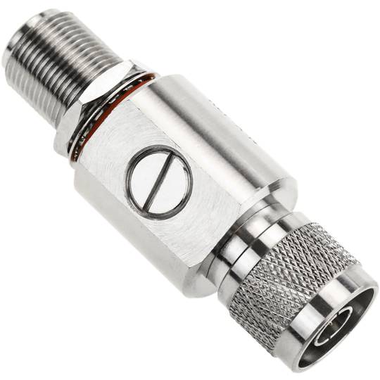
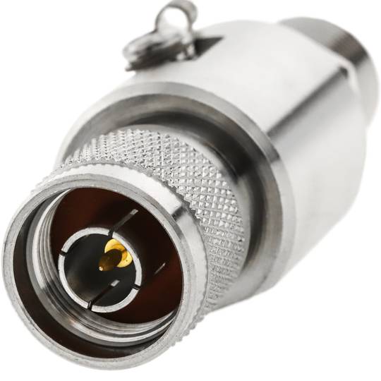
- N-connector based antenna electrical surge protector
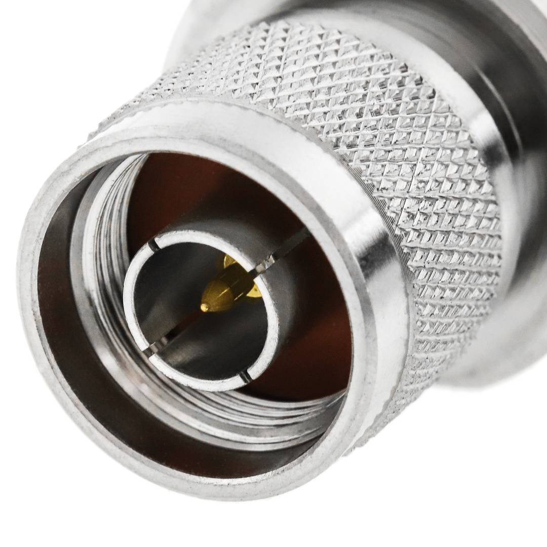
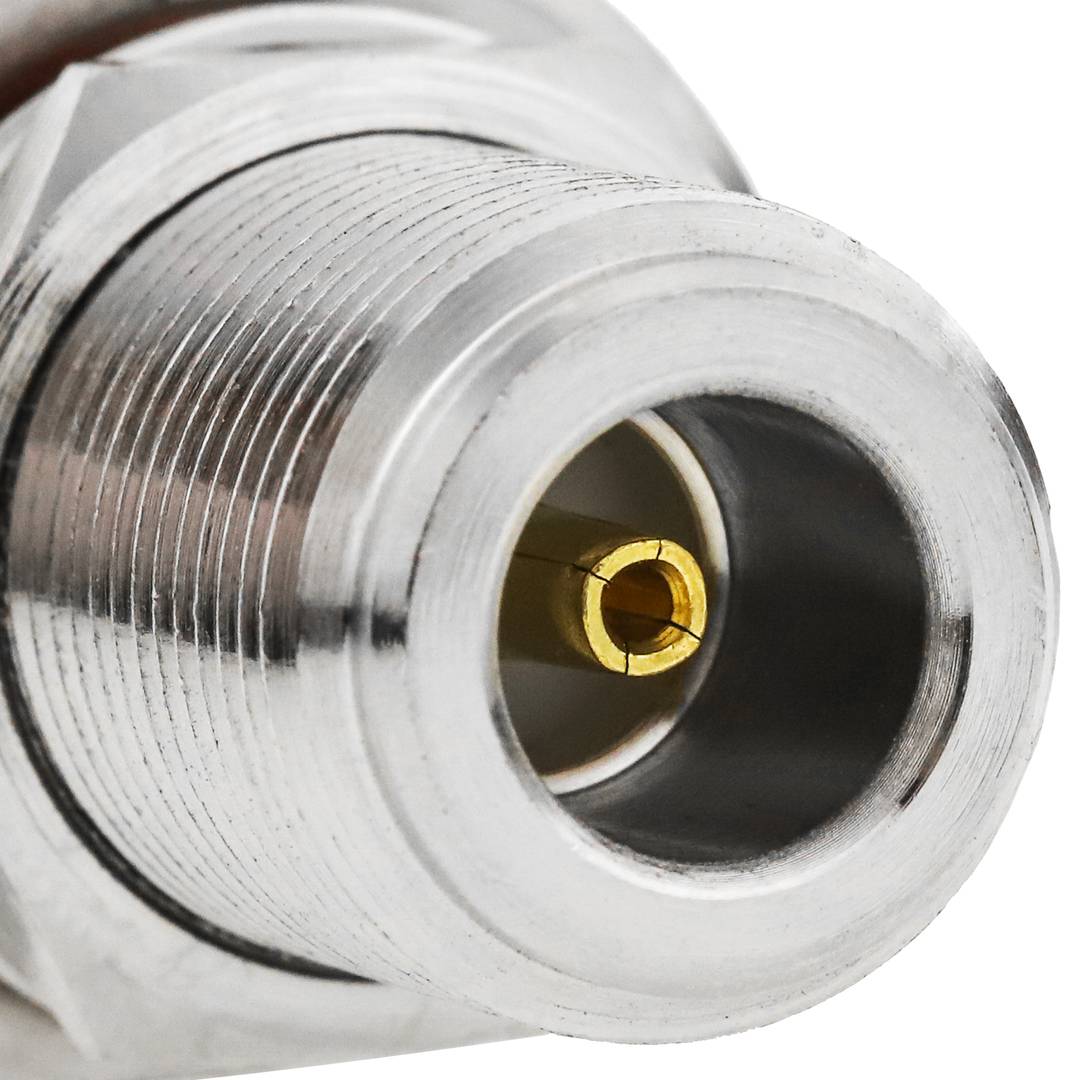
- It has RF connectors type N male to N female for input / output.
- Operating frequency: 0 to 2.5 GHz. Impedance: 50 Ohms. SWR: <= 1.2.
- Operating voltage: 90 V. Transmission power: 300 W.
- Discharge nominal: 5KA. Maximum discharge current: 10KA.
![play_button]() Watch video
Watch video
More info
warranty
returns
safe
- N-connector based antenna electrical surge protector
- It has RF connectors type N male to N female for input / output.
- Operating frequency: 0 to 2.5 GHz. Impedance: 50 Ohms. SWR: <= 1.2.
- Operating voltage: 90 V. Transmission power: 300 W.
- Discharge nominal: 5KA. Maximum discharge current: 10KA.
Related products
Keywords
Did not find what you were looking for? These topic could help you
More info
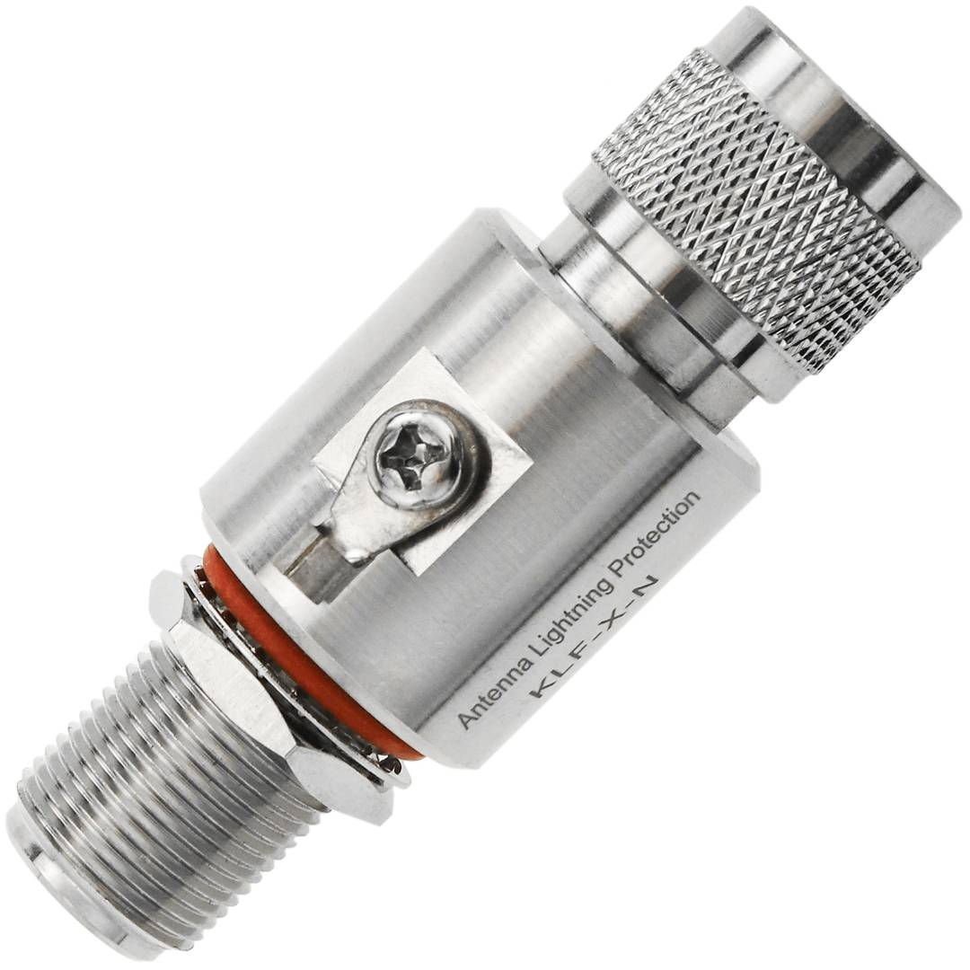
RF antenna electrical surge protector, based on N connectors. N-type input / output terminals connect to this device in pass-through mode without interfering with data transmission. Protects from voltage spikes and electrical surges, induced by lightning, parasites in the electrical network, and other factors. These discharges cause damage to sensitive and delicate electronic equipment connected to the electrical network.
Specifications
- N-connector based antenna electrical surge protector
- It has RF connectors type N male to N female for input / output.
- Operating frequency: 0 to 2.5 GHz. Impedance: 50 Ohms. SWR: <= 1.2.
- Operating voltage: 90 V. Transmission power: 300 W.
- Discharge nominal: 5KA. Maximum discharge current: 10KA.
- Voltage protection level: <= 600 V.
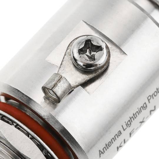
- It has a GND connector.
- Size: 70 x 25 x 27 mm (width x height x depth).
- Gross Weight: 150 g
- Product size (width x depth x height): 7.0 x 2.7 x 2.5 cm
- Number of packages: 1
- Packages size: 10.8 x 4.5 x 3.4 cm
Technical terms
- Impedance
- Hz
Impedance (Z) is the total opposition that a circuit offers to alternating current (AC) flow when a specific voltage is applied.
Unlike simple resistance, impedance is a complex quantity comprising resistance (the real part) and reactance (the imaginary part, representing inductive or capacitive effects). In the frequency domain, impedance is represented as a phasor, accounting for both magnitude and phase shift between voltage and current. In DC circuits, impedance reduces to pure resistance with zero phase angle.
| Parameter | Technical Spec |
|---|---|
| Symbol | Z |
| Unit | Ohm (Ω) |
Impedance management is critical in high-speed hardware design and signal integrity. In modern PCB manufacturing, controlled impedance ensures that high-frequency signals reach their destination without reflections, which is vital for PCIe or DDR5 performance.
Complex Domain Analysis
Mathematical modeling of impedance using the j-operator allows engineers to optimize filter performance and resonance characteristics in electronic systems.
Key Advantages
- Maximum power transfer through impedance matching.
- Minimized signal reflections in high-frequency transmission lines.
- Improved electromagnetic compatibility (EMC).
Note: Impedance is the cornerstone of modern AC circuit theory and high-frequency design.