

https://cablematic.com/en/products/wifi-antenna-coupler-800-to-2500-mhz-10-db-AM013/
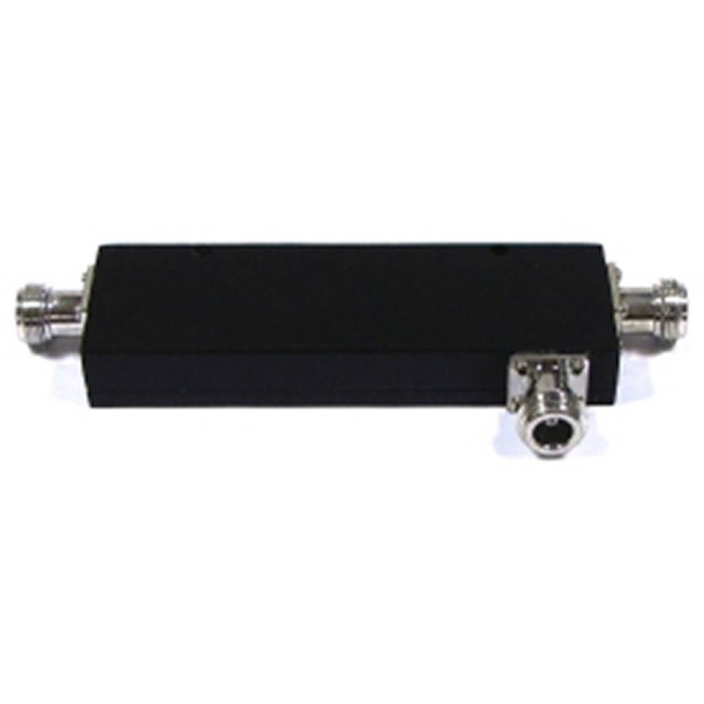
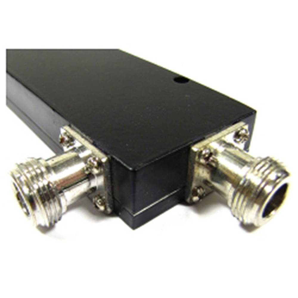
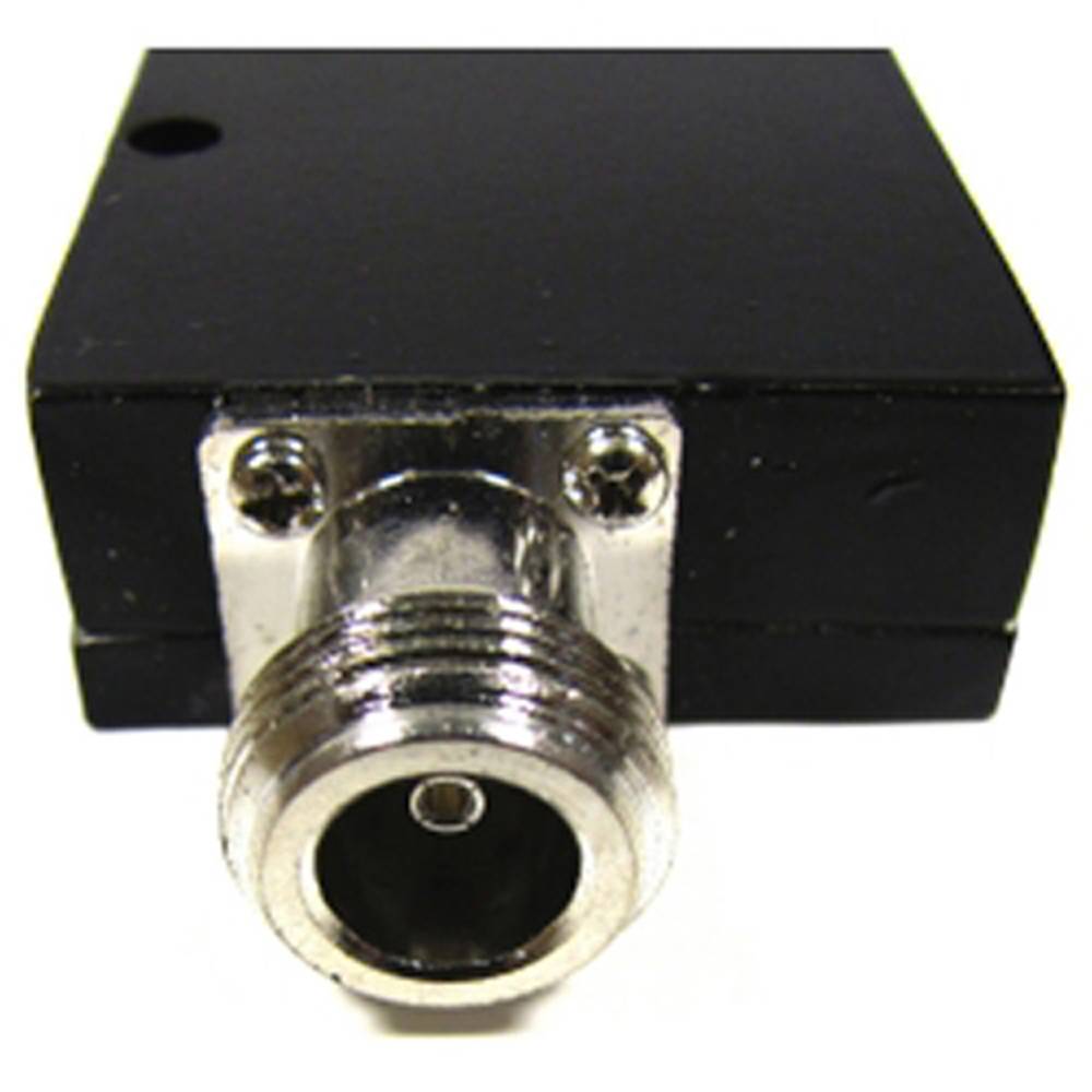


WIFI antenna coupler 800 to 2500 MHz 10 dB

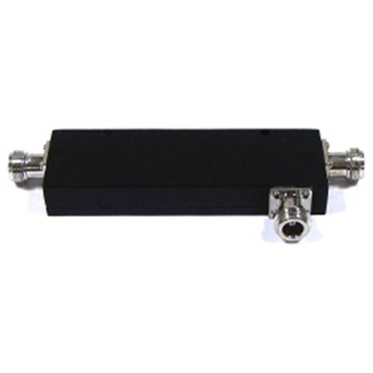
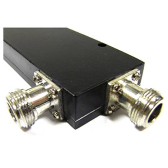
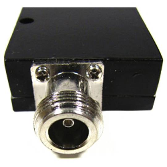
- Frequency range from 800 to 2500 MHz.
- Attenuation: 10 dB.
- Isolation:> = 20 dB.
- Insertion loss: <= 2 dB.
- VSWR: <= 1,2.
 2 years
warranty
 14 days
returns
 100%
100%safe
- Frequency range from 800 to 2500 MHz.
- Attenuation: 10 dB.
- Isolation:> = 20 dB.
- Insertion loss: <= 2 dB.
- VSWR: <= 1,2.
Purchased together regularly
More info
Coupling or coupler for 800-2500 MHz WIFI that allows the installation of two antennas to an access point connector or WIFI electronics. Possibility of configuring the signal power granted to each antenna. Model with 10 dB attenuation.
Specifications
- Frequency range from 800 to 2500 MHz.
- Attenuation: 10 dB.
- Isolation:> = 20 dB.
- Insertion loss: <= 2 dB.
- VSWR: <= 1,2.
- Impedance: 50 Ohm.
- Connectors: 3 x N female.
- Size: 120 x 45 x 17 mm.
- Weight: 200 g
- Gross Weight: 240 g
- Number of packages: 1
Technical terms
- Impedance
- Hz
- Wifi
Impedance (Z) is the total opposition that a circuit offers to alternating current (AC) flow when a specific voltage is applied.
Unlike simple resistance, impedance is a complex quantity comprising resistance (the real part) and reactance (the imaginary part, representing inductive or capacitive effects). In the frequency domain, impedance is represented as a phasor, accounting for both magnitude and phase shift between voltage and current. In DC circuits, impedance reduces to pure resistance with zero phase angle.
| Parameter | Technical Spec |
|---|---|
| Symbol | Z |
| Unit | Ohm (Ω) |
Impedance management is critical in high-speed hardware design and signal integrity. In modern PCB manufacturing, controlled impedance ensures that high-frequency signals reach their destination without reflections, which is vital for PCIe or DDR5 performance.
Complex Domain Analysis
Mathematical modeling of impedance using the j-operator allows engineers to optimize filter performance and resonance characteristics in electronic systems.
Key Advantages
- Maximum power transfer through impedance matching.
- Minimized signal reflections in high-frequency transmission lines.
- Improved electromagnetic compatibility (EMC).
Note: Impedance is the cornerstone of modern AC circuit theory and high-frequency design.