https://cablematic.com/en/products/tv-antenna-coaxial-cable-15m-TT003/


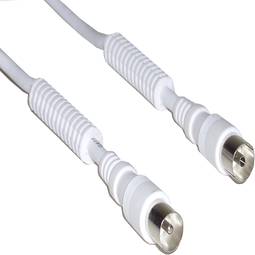
TV Antenna Coaxial Cable (15m)


- Coil 15m coaxial cable for TV antenna 75 Ohms.
- Presented in shrink-wrapped coil for making custom-made cables.
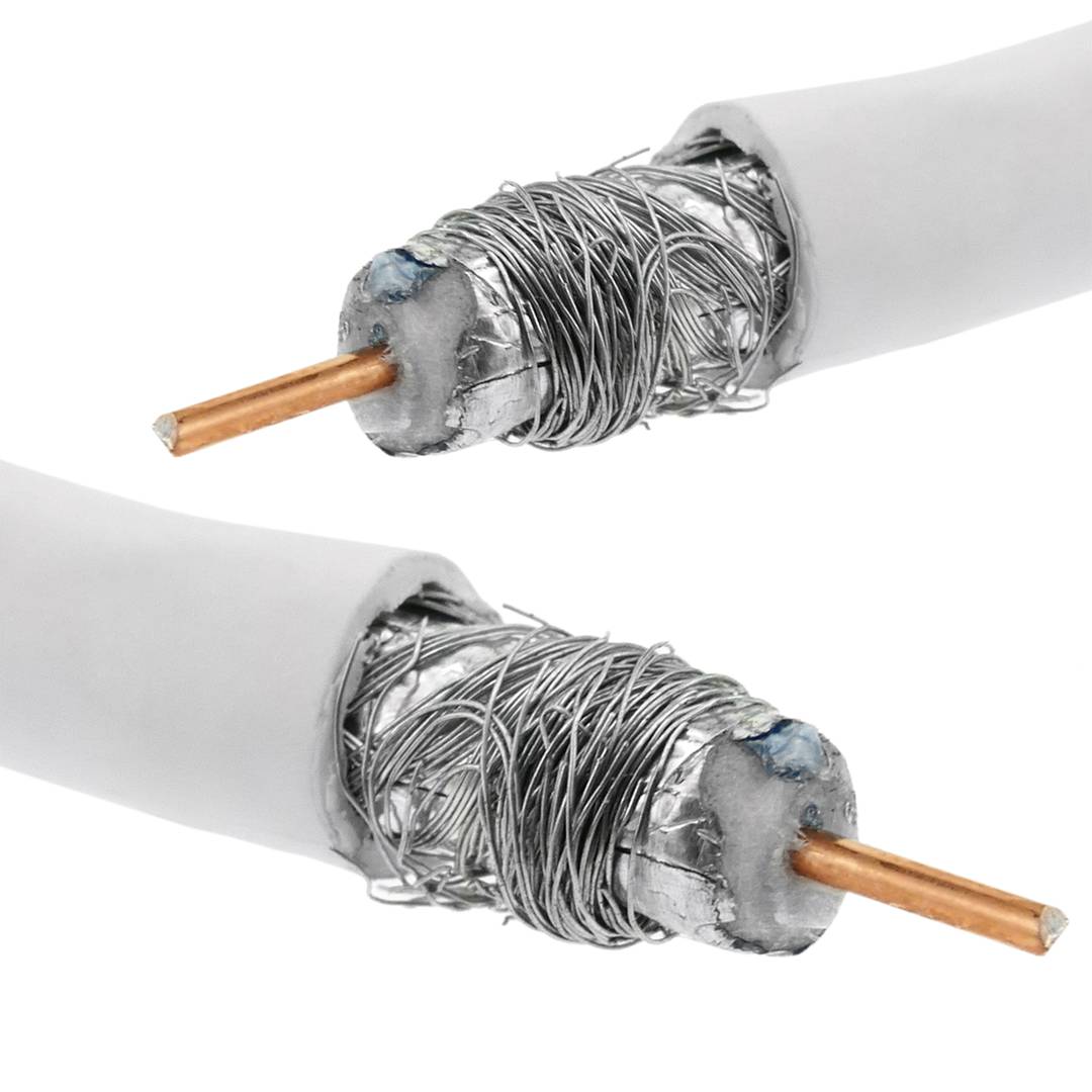
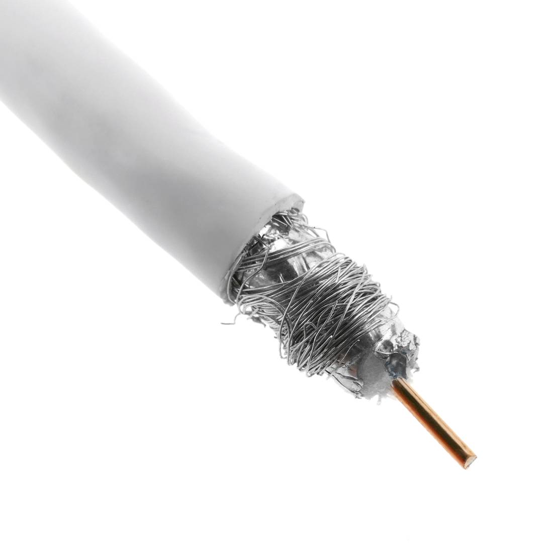
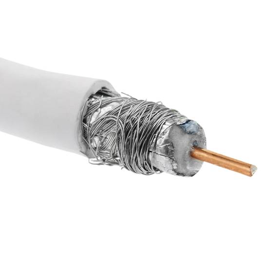
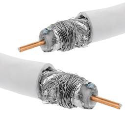
- Circumcentric structure with the following elements (interior to exterior): inner conductor of copper of diameter 1.02mm, insulation PE of diameter 4.57mm, aluminum sheet that covers 100% the interior surface, shielding mesh of aluminum (64/0.12mm) and exterior diameter PVC cover7,02mm Nominal attenuation at 800 MHz of 19 dB/100m.
- White color.
- Cable type: RG6U.
![play_button]() Watch video
Watch video
More info
warranty
returns
safe
- Coil 15m coaxial cable for TV antenna 75 Ohms.
- Presented in shrink-wrapped coil for making custom-made cables.
- Circumcentric structure with the following elements (interior to exterior): inner conductor of copper of diameter 1.02mm, insulation PE of diameter 4.57mm, aluminum sheet that covers 100% the interior surface, shielding mesh of aluminum (64/0.12mm) and exterior diameter PVC cover7,02mm Nominal attenuation at 800 MHz of 19 dB/100m.
- White color.
- Cable type: RG6U.
Related products


Purchased together regularly
More info
Coil 15m coaxial cable for TV antenna 75 Ohms. Presented in shrink-wrapped coil for making custom-made cables. Circumcentric structure with the following elements (interior to exterior): inner conductor of copper of diameter 1.02mm, insulation PE of diameter 4.57mm, aluminum sheet that covers 100% the interior surface, shielding mesh of aluminum (64/0.12mm) and exterior diameter PVC cover7,02mm Nominal attenuation at 800 MHz of 19 dB/100m. White color. Cable type: RG6U.
- Gross Weight: 580 g
- Product size (width x depth x height): 17.0 x 17.0 x 5.0 cm
- Number of packages: 1
- Packages size: 17.0 x 17.0 x 5.0 cm
Technical terms
- Impedance
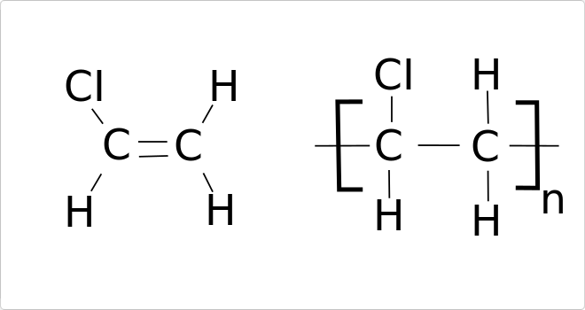
- PVC (Polyvinyl chloride)
- Hz
Impedance (Z) is the total opposition that a circuit offers to alternating current (AC) flow when a specific voltage is applied.
Unlike simple resistance, impedance is a complex quantity comprising resistance (the real part) and reactance (the imaginary part, representing inductive or capacitive effects). In the frequency domain, impedance is represented as a phasor, accounting for both magnitude and phase shift between voltage and current. In DC circuits, impedance reduces to pure resistance with zero phase angle.
| Parameter | Technical Spec |
|---|---|
| Symbol | Z |
| Unit | Ohm (Ω) |
Impedance management is critical in high-speed hardware design and signal integrity. In modern PCB manufacturing, controlled impedance ensures that high-frequency signals reach their destination without reflections, which is vital for PCIe or DDR5 performance.
Complex Domain Analysis
Mathematical modeling of impedance using the j-operator allows engineers to optimize filter performance and resonance characteristics in electronic systems.
Key Advantages
- Maximum power transfer through impedance matching.
- Minimized signal reflections in high-frequency transmission lines.
- Improved electromagnetic compatibility (EMC).
Note: Impedance is the cornerstone of modern AC circuit theory and high-frequency design.