04/26/2024 5:34 a.m.
https://cablematic.com/en/products/spi-to-ethernet-module-t24-model-usr-es1-UK007/
https://cablematic.com/en/products/spi-to-ethernet-module-t24-model-usr-es1-UK007/


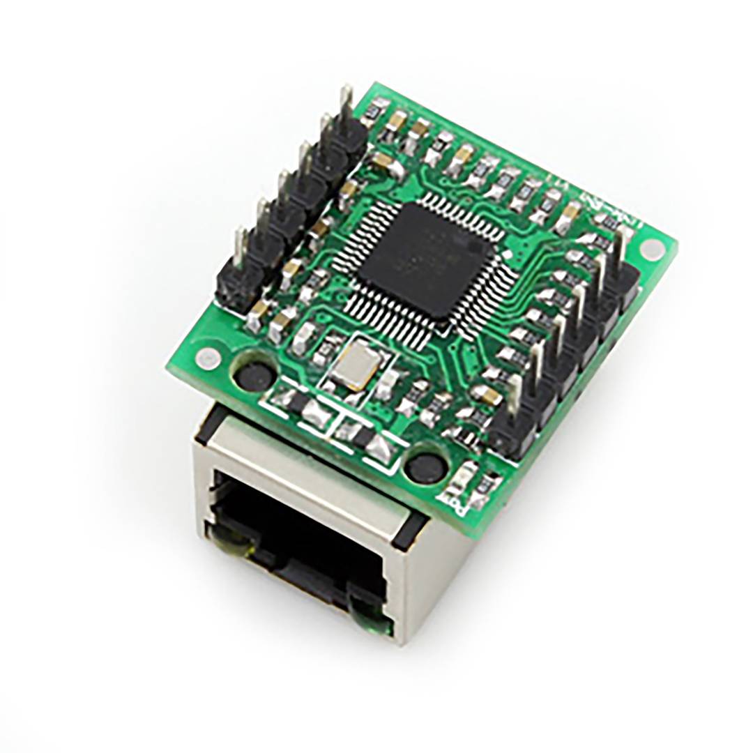
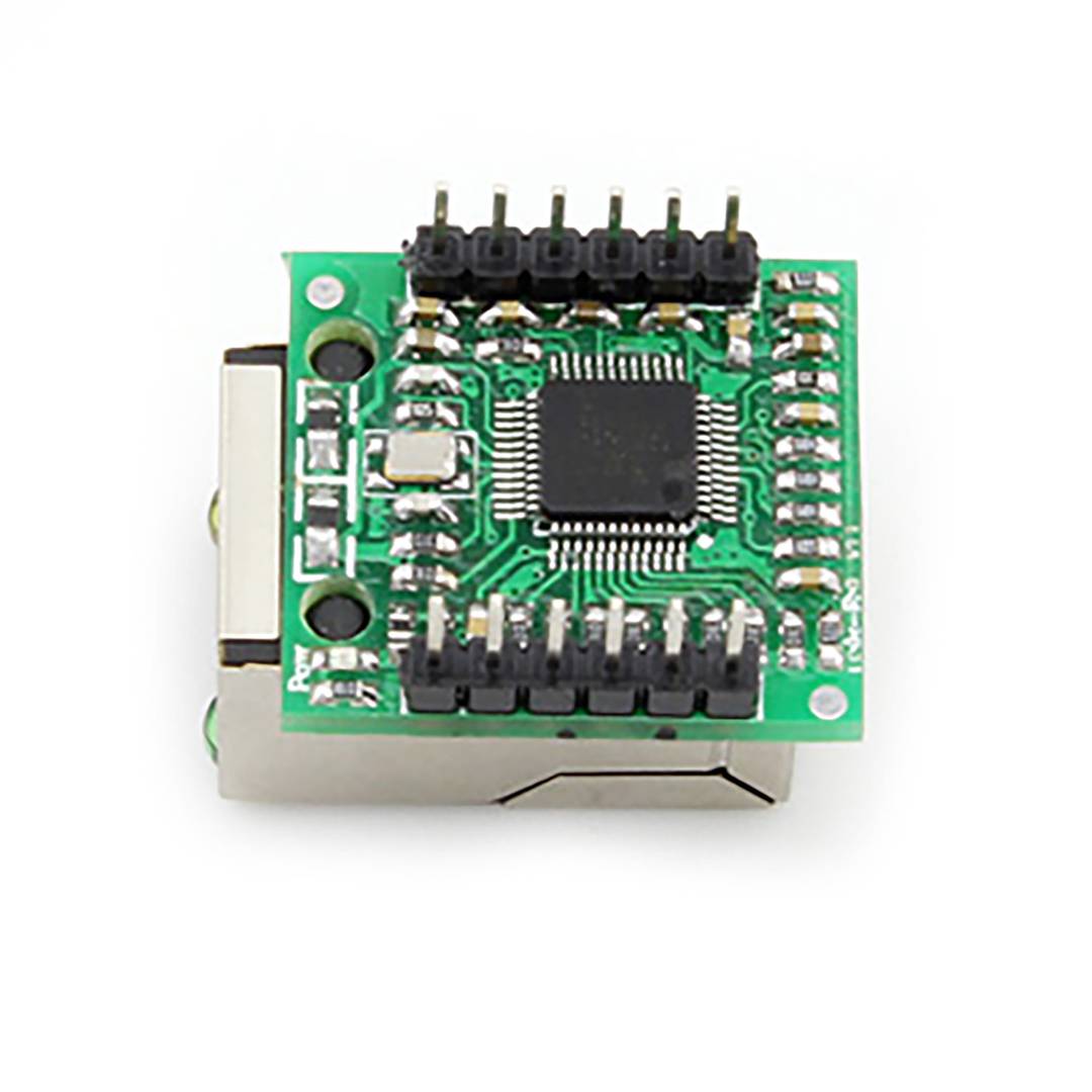

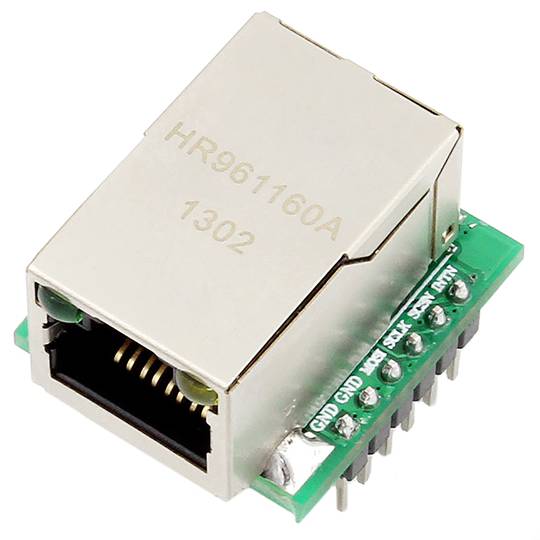
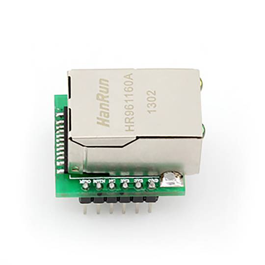
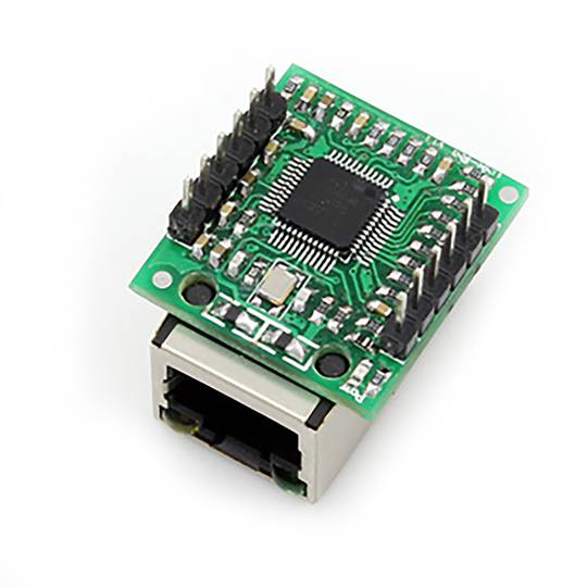
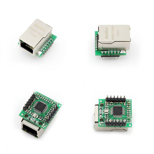
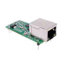
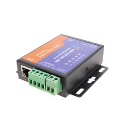
SPI-to-Ethernet Module T24 model USR-ES1


SPI-to-Ethernet Module T24 model USR-ES1
REF: UK007


OUTLET
Specifications
- High-speed interface SPI 80MHz with RJ45 connector.
- TCP/IP hardware protocol.
- Supports up to 8 Sockets
- Support TCP, UDP, ICMP, IPv4, ARP, IGMP, and PPPoE.
- Integration of the data link layer, layer fmusic
PVP
€16.05
€3.37
Price including VAT:
€3.37
PVD
€14.11
€2.96
PVP: Retail price.
Check conditions.
PVP: Sale price to distributors.
Check conditions.
warranty
returns
OUTLET
We will notify you when it is back in stock.
Specifications
- High-speed interface SPI 80MHz with RJ45 connector.
- TCP/IP hardware protocol.
- Supports up to 8 Sockets
- Support TCP, UDP, ICMP, IPv4, ARP, IGMP, and PPPoE.
- Integration of the data link layer, layer fmusic
Related products
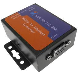
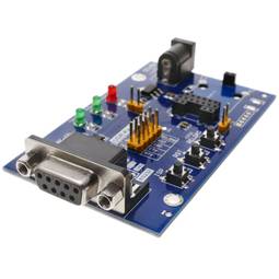
Purchased together regularly
More info
High-speed interface SPI 80MHz with RJ45 connector. Download utilities available on the manufacturer's website. Module of the T24 series.
Specifications
Specifications
- High-speed interface SPI 80MHz with RJ45 connector.
- TCP/IP hardware protocol.
- Supports up to 8 Sockets
- Support TCP, UDP, ICMP, IPv4, ARP, IGMP, and PPPoE.
- Integration of the data link layer, layer fmusic
- Support for high speed serial peripheral interface (SPI model 0.3).
- Internal buffer of 32K.
- Physical ethernet layer: 10BaseT/100BaseTX (PHY).
- Automatic negotiation support (10/100-base full duplex or half duplex).
- Does not support the IP patch.
- Operating voltage of 3.3V and 5.0V.
- Gross Weight: 10 g
- Number of packages: 1
Technical terms
- RJ45
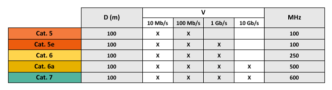
- Categories network cables
RJ45
When we talk about RJ45 ("Registered Jack" 45) we refer to a telecommunications network interface for wired connection of voice and data equipment.
This connector has 8 pins or connections and may have a specific category depending on the data transfer speed and bandwidth (category 5e, 6, etc.)
The common application is their use in Ethernet network cables under TIA/EIA-568-B standard that defines the arrangement of pins (pinout), but can also be used for other applications.
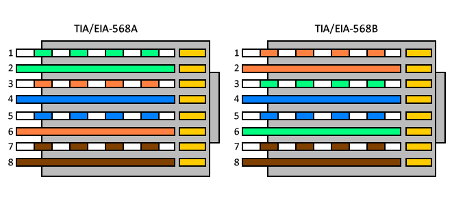
- Direct pin diagram:
EIA-568A
Pin No.1: WHITE-GREEN
Pin No.2: GREEN
Pin No.3: WHITE-ORANGE
Pin No.4: BLUE
Pin No.5: WHITE-BLUE
Pin No.6: ORANGE
Pin No.7: WHITE-BROWN
Pin No.8: BROWN
EIA-568B
Pin No.1: WHITE-ORANGE
Pin No.2: ORANGE
Pin No.3: WHITE-GREEN
Pin No.4: BLUE
Pin No.5: WHITE-BLUE
Pin No.6: GREEN
Pin No.7: WHITE-BROWN
Pin No.8: BROWN
- Schematic of crossed pins:
The crossover cable has one end with EIA-568A scheme and the other one with EIA-568B.
This connector has 8 pins or connections and may have a specific category depending on the data transfer speed and bandwidth (category 5e, 6, etc.)
The common application is their use in Ethernet network cables under TIA/EIA-568-B standard that defines the arrangement of pins (pinout), but can also be used for other applications.
- Direct pin diagram:
EIA-568A
Pin No.1: WHITE-GREEN
Pin No.2: GREEN
Pin No.3: WHITE-ORANGE
Pin No.4: BLUE
Pin No.5: WHITE-BLUE
Pin No.6: ORANGE
Pin No.7: WHITE-BROWN
Pin No.8: BROWN
EIA-568B
Pin No.1: WHITE-ORANGE
Pin No.2: ORANGE
Pin No.3: WHITE-GREEN
Pin No.4: BLUE
Pin No.5: WHITE-BLUE
Pin No.6: GREEN
Pin No.7: WHITE-BROWN
Pin No.8: BROWN
- Schematic of crossed pins:
The crossover cable has one end with EIA-568A scheme and the other one with EIA-568B.